This article may be regarded as a quick reference to laboratory staff who are wishing to develop their own microscopy system for self-service and modernization of the system and in order to save the lab budget.
INTRODUCTION
Today one of the main areas of application of multiphoton microscopy is biology. This is due to the fact that this technique allows to obtain 3D images of tissues due to laser focus change, that is possible due to substantially greater penetration depth on the main wavelength into biological tissues. However, there are certain peculiarities arising from the specifics of experiments using this technique. In one case, for example, the analysis of the morphological cell data of hippocampal slices of the brain of rodents, other experiments in vivo depending on the design using the full-sphere of the virtual reality or, for example, in the form of a cylindrical hover platform. Specific features are also in the fact that the level of fluorescence-activated objects is low (only a few suites), and the increase of the laser intensity may overheat and burn the sample. Sample scan methods are constantly changing, and require constant modernization. Creation of two-photon system taking into account it specific use in neuroscience is probably the best solution.
THE CONSTRUCTION OF THE MICROSCOPE
The three-dimensional model of future microscope was developed using software Compass (Figure 1). The model depicts the main frame (Figure 1, 1), attached to the vibration free table, as well as optical elements, attached to the main frame. Technically, the operation of differential interference contrast (DIC) is provided with installation of a visible light source (figure 1, 2) and an IR filter, an iris-shutter, a diffuser, a mirror to reflect the beam in the vertical direction and lens (Figure 1, 3). After passing through the lower block and being reflected the light beam reaches the polarizer, and then passes onto a condenser (Figure 1, 4) with Nomarski prism. Then a laser beam achieve the sample, which is fixed on the table (Figure 1, 5). The table, in turn, is fixed to a U-shaped moving platform (Figure 1, 6) for exact positioning of the sample under the lens in the lateral plane. Passing through the sample, the beam achieve the optical components on a moving platform (fixed to the frame of the microscope) (Figure 1, 7), and passes the second Nomarski prism and the analyzer. Here the interference of previously separated rays is performed. After passing the mentioned optical path the light beam falls onto the so-called illuminator of reflected light (Figure 1, 8), that does not contain any filters or mirrors in the DIC mode operation, and then the beam passes onto IR camera (Figure 1, 9) that displays the image on the monitor. Principal scheme of the two-photon microscope system is presented at the Figure 2. As the laser source is using femtosecond IR Ti:Sa laser (Figure 2, L1). The range of the wavelength is from 690 to 1080 nm. The laser beam is starting from the laser aperture and passing the optical path including acousto-optic modulator (AOM) to change the radiation intensity and the Galileo type telescope to changing the diameter of the beam. After that the beam enters into the vertical optical bar with a mirror (Figure 2, 14) which reflect the beam to the next mirror (Figure 2, 13) which deliver laser beam to the desired height.
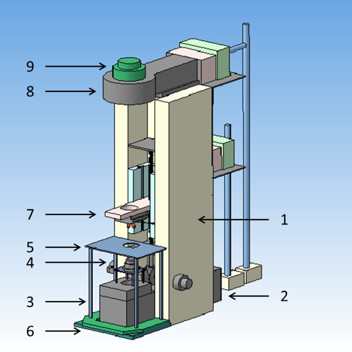
Fig.1. The three-dimensional model of future microscope.
Further, the beam enters to the resonant scanning unit using a synchronous operation of the mirror and the resonant galvanometer (Figure 2, 14, 15) and the focusing lens (Figure 2, 16) scans the sample. The parameters of the scanner are controlled by the PC. Reflecting by the mirrors (Figure 2, 17, 18) beam achieve dichroic mirror (Figure 2, 19) transmitted the beam falling on it from the scanning laser (Figure 2, L1) and reflects from activating the laser (Figure 2, L2). Then the beam is focusing in the desired plane by the height of objective (Figure 2, 7) and achieve the sample (Figure 2, 6) activating fluorescence at the desired point, and point by point scans the sample. Aperture lens is capturing fluorescent photons (Figure 2, 7) reflected by the dichroic mirror (Figure 2, 22), pass filters (Figure 2, 23, 27, 28) and the falling to the non-descanned detectors (NDD). Distance from the sample to the light detector is about 10 centimeters, which allows to register low level of fluorescence. The optical path of the laser beam from activating laser (Figure 2, L2) is similar to the path from the laser scanning (Figure 2, L1), however in this case using the scanning element including a pair of mirror galvanometers (Figure 2, CK2).
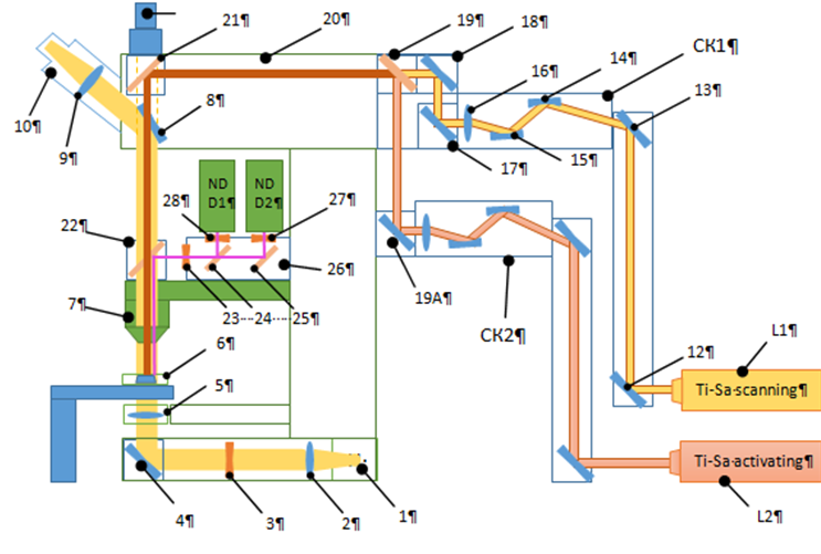
Fig.2. Principal scheme of the two-photon microscope system.
| Attachment | Size |
|---|---|
| 336.63 KB |
This work was supported by the Ministry of education of Russian Federation, unique identity number of the project is RFMEFI57814X0079.
