Synchrony in neuronal networks plays a crucial role in the functioning of the brain. Stability of synchrony is most desirable to prevent any emergent desynchrony due to natural events, internal or external disturbances. The brain might have its own mechanism to repair its desynchrony, otherwise, some external procedure might be necessary to restore synchrony. We propose here a mechanism to realize robust synchrony in neuronal networks against parameter drifting. A selective addition of cross-coupling links over and above the conventional diffusive coupling links is found [Saha et al. (2017)] recently that makes dramatic improvements in the stability of synchrony of dynamical networks and that saves synchrony against breakdown due to parameter drifting. We apply the concept to realize globally stable synchrony in neuronal networks and the desired effect of robust synchrony and, present our numerical studies with examples of network motifs and a larger network of neurons and using the Hindmarsh-Rose (HR) [Hindmarsh and Rose (1984)] slow-fast neuron model for each node of the networks.

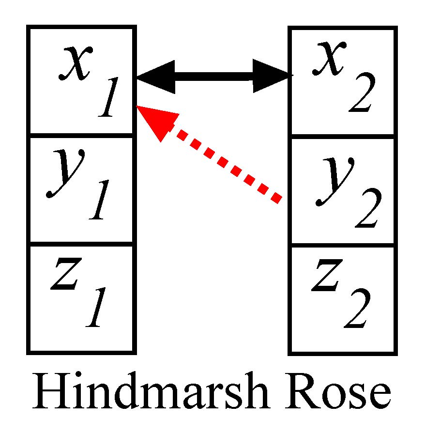
Figure 1. Two coupled neurons (schematic diagram at left panel). Synchronization manifold (black line for CS and red line for GS) is projected in the y1-y2 plane at right panel. Parameters are chosen in the chaotic dynamical regions for both the systems: a = 3, I = 3.25, d = 5, µ = 0.006, r = 4, c = 1.6, b1 = 0.5, b2 = 1. ɛ1 = 0.45 and ɛ2 = 1.
The selected coupling profile (diffusive self-coupling and cross-coupling functions) favors global stability of synchrony in the two-coupled neuron model. Analytical details are provided in the Appendix to derive the condition for the coupling strengths, \(\varepsilon_1\leq a^2/6\) and \(\varepsilon_2=1\), when a globally stable complete synchronization (CS) state i.e., \(x_1=x_2\) \(y_1=y_2\) and \(z_1=z_2\) emerges for the coupled neurons. This condition explains that both the neurons oscillate in complete coherence of amplitude and phase. The amplitudes and phases of the neurons remain same all the time. The synchronous state is clearly globally stable as proved in the Appendix; it is stable for any choice of initial conditions from the basin of attraction of the coupled system. Numerical results are presented in the right panel of Fig. 1 for two identical neurons. The 2D projection of the synchronization manifold of identical neurons is shown in a black line. The red line also confirms a synchronous state, but it is a type of generalized synchronization (GS) [Abarbanel et al. (1996)] that emerges for a parameter perturbation. This is also globally stable which is never possible under a simple diffusive self-coupling. For illustration, we introduce a parameter mismatch i.e., (b1 ≠ b2), when the globally stable GS state defined by \(x_1=x_2\),\(y_1 \cdot \frac{b_1}{b_2}=y_2\) and \(z_1=z_2\) emerges (see Appendix). We note that x1,2 and z1,2 variables achieve an identical state similar to the CS case, however, y1 and y2 variables are not identical, but develop a linear relation where the linearity constant depends upon the ratio of the system parameters of the neurons. In the right panel of Fig. 1, a 2D projection of the GS manifold (red line) of the detuned systems shows a rotation from the CS manifold. A transition from CS to GS state simply occurs due to the parameter perturbation. This indicates that if a parameter of one neuron is drifted or changed, the CS state simply transits to the GS state without a loss of overall coherence or synchrony. One of the state variables of the perturbed neuron is either amplified or attenuated depending upon the value of the detuned parameter. The GS thus can be viewed as an amplitude response of the detuned system’s attractor [Saha et al. (2017)] under parameter perturbation. This phenomenon is further explained in the next section.

 is the adjacency matrix that defines the topology or structure of any network, in general, via the self-coupling links.
 is the connectivity matrix of the additional cross coupling links of the network; Aij = 1 and Bij = 1, if i-th node is connected to the j-th (j ≠ i) and 0 otherwise. B is selected from A: the directed cross-coupling links are connected from the maximum outdegree node to all the other nodes so that the network structure remains unaltered. and are the strength of self- and cross-coupling links, respectively, between any two nodes whose values are analytically derived from Lyapunov stability of synchrony.
\(\varepsilon_1=1.9\) and \(\varepsilon_2=1\) are taken for the 3-, 4-node motifs and the 16-node network.
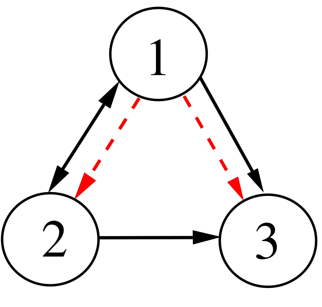
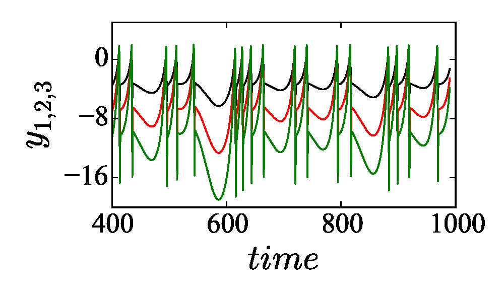
We consider a 3-node motif first as shown in the upper left panel of Fig. 2 with three self-coupling links (black arrows), two directed links and one bidirectional link. The addition of two directed cross-coupling links (red dashed arrows) is suggested by our proposed strategy [Saha et al. (2017)] that makes synchronization globally stable and robust to parameter perturbation. Accordingly, we change Aij and Bij in Eq. (2) to define the dynamics of the 3-node motif. In upper right panel, the 2D projection of the attractors of three nodes are drawn for different values of b1 = 1, b2 = 2 and b3 = 3 in black, red and green, respectively, which depicts increasing enlargement of the attractors along the yi direction. The enlargement increases with positive detuning of parameters in the nodes (node 2 and 3). For three identical nodes, all the attractors collapse on the black attractor when a globally stable CS in the motif is established (analytical proof is not presented here). For all three different nodes, an overall coherence is maintained between the three nodes; three different attractors (black, red and green) with different amplification constant are seen for positive detuning of the parameters. This state is defined as the GS state and it is also globally stable. Thus parameter mismatches in three nodes do not break the synchrony. Lower panel shows the corresponding yi time series of three nodes where all the oscillations are perfectly in phase, but different in amplitude depending upon the value of the detuned parameter of a particular node. Note that other state variables x1,2,3 and z1,2,3 remain identical similar to the example of two coupled neurons given in the previous section. Results support our desired target that the 3-node motif is globally stable in a CS state by the addition of the cross-coupling links when they are all identical. For all perturbed nodes, represented by their different parameters, the motif transits to a GS state which is also globally stable; there is no loss of overall synchrony.
Figure 2. A 3-node network motif (upper left panel). Black arrows for self-coupling links and red arrows for cross-coupling links. Upper right panel shows 2D phase portraits in the \(x_i-y_i\) plane of three neurons for \(b_1=q, b_2=2\) and \(b_3=3\) in black, red and green, respectively. Lower panel shows \(y_i\) time series of three neurons.
The adjacency matrix A and the connectivity matrix B are given for the 3-node motif,
\(A= \begin{pmatrix} 0 & 1 & 0 \\ 1 & 0 & 0 \\ 1 & 1 & 0 \end{pmatrix}; B=\begin{pmatrix} 0 & 0 & 0 \\ 1 & 0 & 0 \\ 1 & 0 & 0 \end{pmatrix}; \)
and for the selected 4-node motif,
\(A= \begin{pmatrix} 0 & 1 & 1 & 0 \\ 1 & 0 & 1 & 0 \\ 1 & 1 & 0 & 0 \\ 1 & 1 & 1 & 0 \end{pmatrix}; B=\begin{pmatrix} 0 & 0 & 0 & 0 \\ 1 & 0 & 0 & 0 \\ 1 & 0 & 0 & 0 \\ 1 & 0 & 0 & 0 \end{pmatrix}. \)
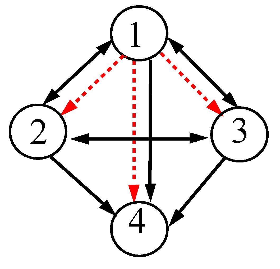
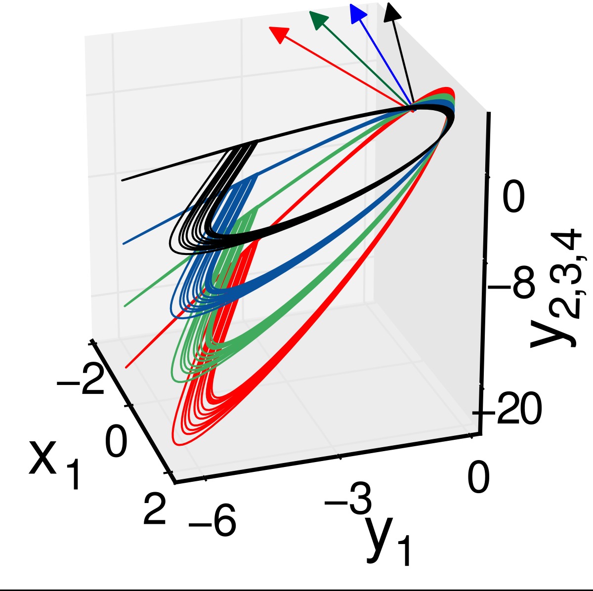
Similarly, for a 4-node motif shown in the left panel of Fig. 3, we follow the same strategy of applying the cross-coupling links (red dashed arrows). From the beginning, we assume that all the nodes are perturbed by their parameters \(b_i\)(i=1, 2, 3, 4). On the right panel, the synchronization hyperplanes of the detuned oscillators (blue, green and red) against the identical state (black line) are presented. A comparison clearly shows that the synchronized attractors are gradually enlarged with increasing value of the parameter \(b_i\).
Figure 3. A 4-node network motif (left panel). Solid (black) and dashed (red) arrows represent self- and cross-coupling links, respectively. Right panel: projection of synchronization hyperplanes. Color arrows show rotation along the transverse direction to their respective hyperplanes. Parameters are b1=1, b2=2, b3=3, b4=4, respectively, for black, blue, green and red hyperplanes. \(\varepsilon_1=1.9\) and \(\varepsilon_2=1\)
The 4-node motif attains a GS state that remains globally stable. The color arrows indicate the transverse direction to the synchronization hyperplanes, which clearly shows their rotational effect with increasing parameter mismatch. We repeat that all the nodes collapse to the synchronization hyperplane in black when they are identical and attain a globally stable CS state, as described above for previous two examples.
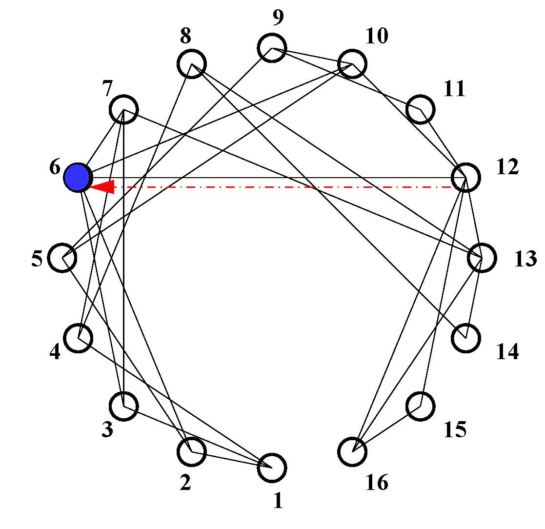
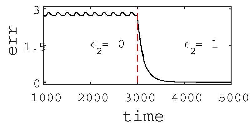
The effect of globally stable synchrony and its robustness to parameter perturbation is also noticed in a larger network with 16-node as shown in the upper panel of Fig. 4. The original network is defined by its nodes and bidirectional self-coupling (black links) which is assumed synchronous for a coupling strength \(\varepsilon_1\)(=1.9) larger than a critical value. However, if we detune the parameter of any one of the nodes, say, b6 of node-6 (blue node), with respect to the other nodes, the synchrony in the network is lost. By adding one directed cross coupling link (red dashed arrow) from any of its neighbors (say, from node-12 to node-6), the synchrony is restored, which is shown in the lower panel of Fig. 4. Synchronization in the network is monitored by defining an error,
\(err(t)=\sqrt{\sum_{i=2}^{N} } [(x_1 - x_i)^2(z_1-z_i)^2]\) , where N is the network size. err(t )≠0 means no synchronization. The synchronization error (err) is large before adding the cross-coupling link (\(\varepsilon_2=0\)) and becomes 0 when the cross-coupling link is added (\(\varepsilon_2=1\)). Addition of a cross-coupling link restores synchrony immediately.
We are yet to prove its global stability. In fact, a transition from the original CS state (before addition of the cross-coupling link) to a GS state (after the addition) is also seen, but we do not elaborate it here. We present here only the constructive role of a cross-coupling link that is clear from our numerical result.
Figure 4. Upper panel shows schematic diagram of a network. Node-6 (blue node) is perturbed while all other nodes have identical parameters. To restore synchrony only one directed cross-coupling link (dashed red arrow) is added to node-6 from a neighbor node-12. In the lower panel, time series of the synchronization error (err) shows that in absence of the cross-coupling link (\(\varepsilon_2=0\)), synchrony is lost when node-6 is perturbed (b ≠ b6 = 2). At t ≥ 3000, one directed cross-coupling link (\(\varepsilon_2=1\)) is added from node-12 to node-6, synchrony is restored (err = 0) in the network.

| Attachment | Size |
|---|---|
| 500.91 KB |
S.S is supported by the SERB-DST (India), A.M is supported by the University Grants Commission (India). P.K.R. acknowledges support by the CSIR (India) Emeritus scientist scheme and S.K.D. is supported by the University Grants Commission (India) Emeritus Fellowship.
Abarbanel, H. D., Rulkov, N. F., and Sushchik, M. M. (1996). Generalized synchronization of chaos: The auxiliary system approach. Physical Review E, 53(5):4528.
Boccaletti, S., Kurths, J., Osipov, G., Valladares, D., and Zhou, C. (2002). The synchronization of chaotic systems. Physics reports, 366(1):1–101.
Hindmarsh, J. L. and Rose, R. (1984). A model of neuronal bursting using three coupled first order differential equations. Proceedings of the royal society of London B: biological sciences, 221(1222):87–102.
Milo, R., Shen-Orr, S., Itzkovitz, S., Kashtan, N., Chklovskii, D., and Alon, U. (2002). Network motifs: simple building blocks of complex networks. Science, 298(5594):824–827.
Mirollo, R. E. and Strogatz, S. H. (1990). Amplitude death in an array of limit-cycle oscillators. Journal of Statistical Physics, 60(1):245–262.
Padmanaban, E., Saha, S., Vigneshwaran, M., and Dana, S. K. (2015). Amplified response in coupled chaotic oscillators by induced heterogeneity. Phys. Rev. E, 92:062916.
Pecora, L. M. and Carroll, T. L. (1998). Master stability functions for synchronized coupled systems. Physical review letters, 80(10):2109.
Pikovsky, A., Rosenblum, M., and Kurths, J. (2003).Synchronization: a universal concept in nonlinear sciences, volume 12. Cambridge university press.
Rosenblum, M. G., Pikovsky, A. S., and Kurths, J.(1996). Phase synchronization of chaotic oscillators. Physical review letters, 76(11):1804.
Roy, P. K., Chakraborty, S., and Dana, S. K. (2003). Experimental observation on the effect of coupling on different synchronization phenomena in coupled nonidentical chua’s oscillators. Chaos: An interdisciplinary Journal of Nonlinear Science, 13(1):342–355.
Saha, S., Mishra, A., Padmanaban, E., Bhowmick, S. K., Roy, P. K., Dam, B., and Dana, S. K. (2017). Coupling conditions for globally stable and robust synchrony of chaotic systems. Physical Review E, 95(6):062204.
Saxena, G., Prasad, A., and Ramaswamy, R. (2012). Amplitude death: The emergence of stationarity in coupled nonlinear systems. Physics Reports, 521(5):205–228.
Singer, W. (1993). Synchronization of cortical activity and its putative role in information processing and learning. Annual Review of Physiology, 55(1):349–374. PMID: 8466179.
Sporns, O. (2010). Networks of the Brain. MIT press.
Sporns, O. (2013). Structure and function of complex brain networks. Dialogues in clinical neuroscience, 15(3):247

